

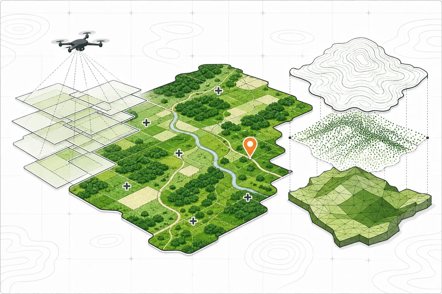
Drone mapping software turns overlapping aerial photographs into measured, georeferenced outputs. These may include an orthomosaic, elevation model, point cloud or textured three-dimensional model. The software is only one part of the process: useful results also depend on a clear brief, suitable capture conditions, sound positioning data and independent checks.
This guide explains how to choose a platform, plan a mission, process imagery and assess the result. It focuses on practical decisions that remain relevant across surveying, construction, land management, agriculture and environmental monitoring.
Define the required result first
Begin with the decision the map must support. A visual site record needs a different level of control from an earthworks calculation or a boundary survey. Write down the deliverable, required coordinate reference system, acceptable error, coverage area, deadline and intended users before comparing software.
Common outputs
- Orthomosaic: a corrected image assembled from many photographs and aligned to map coordinates. It supports inspection, digitising and plan-view measurements.
- Digital surface model: an elevation grid that includes visible buildings, trees, vehicles and other surface objects.
- Digital terrain model: an attempted representation of bare ground after surface features have been classified and removed.
- Point cloud: a collection of three-dimensional points used for classification, measurement and further modelling.
- Textured mesh: a connected surface with image detail, useful for viewing structures and complex sites.
- Derived measurements: contours, slopes, areas, distances, cut-and-fill values and stockpile volumes calculated from validated source data.
A polished output is not automatically an accurate one. Software can smooth gaps or create a convincing surface from weak imagery. The project specification should therefore distinguish visual completeness from positional and measurement accuracy.
Evaluate the complete workflow
Do not choose a platform from its feature list alone. Test the route from flight planning to final export with a small representative dataset. Include the people who will capture images, process them, check accuracy and use the delivered files.
Capture and hardware support
Confirm that the system supports the aircraft, camera and positioning method already in use. Check whether flight planning works with the controller, whether image metadata is read correctly, and whether the processor accepts real-time or post-processed positioning records. Special sensors may need calibration data and dedicated processing steps.
Compatibility has two parts. A processor may accept photographs from a camera without being able to plan flights for its aircraft. It may also handle ordinary colour images but lack the calibration needed for thermal or multispectral analysis. Run a trial rather than relying on a broad compatibility statement.
Processing and quality controls
Useful controls include camera calibration, ground-control marking, coordinate-system selection, image-quality warnings and an accuracy report. The interface should show failed images and processing stages clearly. Reviewers also need access to residuals, checkpoints and any settings that materially affect the output.
Automation can make routine jobs easier, but it should not hide the assumptions behind a measurement. A team handling irregular terrain, reflective surfaces or complex structures may need manual controls that a simple browser workflow does not expose. This drone mapping software overview describes several processing stages, but the final assessment should use the team’s own data and acceptance criteria.
Deployment and data control
Browser-based processing can simplify sharing and reduce workstation requirements. Local processing can suit sensitive projects, unreliable connections or teams that need direct control of storage and versions. In either case, check upload and download limits, supported export formats, access permissions, backup options and the procedure for retrieving all project data.
Estimate storage from raw images, positioning logs, intermediate files and final outputs, not only the delivered map. Large point clouds and meshes can exceed the size of the original photographs. Hardware trials should use a realistic image count so that memory, graphics processing, disk space and processing time can be assessed before a live project.
Plan and capture the mission
Set the flight pattern
Flight altitude, camera angle and image overlap follow from the required ground detail and subject. Nadir photographs suit terrain and plan views. Oblique images provide more information about façades, stockpiles and other vertical surfaces. Complex terrain, uniform surfaces and tall structures may require extra overlap or crossing flight lines.
Keep exposure and focus consistent where conditions allow. Motion blur, glare, deep shadow and large lighting changes make image matching less reliable. Wind can tilt the aircraft or move vegetation between frames. A short test flight can reveal these problems before the full site is covered. Existing Drone mapping flight-planning guidance can supplement, but not replace, a site-specific safety and capture plan.
Before launch, confirm:
- the site boundary, obstacles, take-off and landing areas, airspace and weather;
- the required ground detail, flight height, camera angle and overlap;
- camera focus, exposure, time settings and image geotagging;
- battery reserves and a safe response to interruption or changing conditions;
- control and checkpoint locations, visibility and coordinate records.
Use control and checkpoints correctly
Ground control points are visible targets with surveyed coordinates that constrain the model. Distribute them around the project and across meaningful changes in elevation. Mark each target in enough sharp photographs and verify that imported coordinates use the intended horizontal and vertical reference systems.
Checkpoints serve a different purpose. They are withheld from the adjustment and compared with the completed model, providing an independent test of positional error. A low residual on control points only shows how closely the model fits the points used to build it; it does not replace checkpoint evidence.
Real-time and post-processed positioning can improve camera coordinates and reduce reliance on control for some work. They do not remove the need to check the result when accuracy matters. Record the correction source, base coordinates, antenna settings, geotagging process and any lost correction periods.
Address rules and privacy
Operators must review the aviation, land-access, privacy and environmental rules that apply to each location. Mapping software may help store mission records, but it does not grant permission to fly or collect imagery. In the United States, the Federal Aviation Administration publishes official airspace guidance; elsewhere, consult the relevant national and local authorities.
Limit capture to the defined work area. Consider nearby homes, faces, vehicle plates, schools, critical infrastructure and wildlife. Avoid unnecessary camera angles, restrict access to raw imagery and set a retention period based on the project’s actual needs.
Process without losing traceability
Prepare the inputs
Copy original photographs and logs into read-only storage before processing. Remove unusable frames only from the working set, keeping a note of what was excluded and why. Check for blur, missing geotags, repeated files, changing focal length, propellers in view and major exposure differences.
Define the coordinate reference system before importing control. Horizontal datum, projection, units, vertical datum and geoid model must be compatible across camera positions, control points and exports. A clean-looking model can still be displaced when one dataset uses a different reference.
Inspect the result
Review the orthomosaic at full detail for seams, doubled features, warped edges, holes and blurred areas. Examine the point cloud from several angles for noise, incomplete surfaces and vegetation artefacts. Compare checkpoints and report horizontal and vertical errors in the project’s working units. Examples of audit-ready accuracy reports may help structure a record, but the stated tolerance must come from the project brief.
Repeat measurements on a few known features. For volume work, inspect the boundary and reference surface rather than accepting the first calculated value. For repeat surveys, use consistent control, capture settings and processing choices so that apparent change is less likely to be a workflow difference.
Stop and investigate when:
- checkpoints exceed the agreed tolerance or show a directional pattern;
- large areas have weak image alignment or missing coverage;
- the coordinate system or vertical reference cannot be confirmed;
- measurements change materially after small boundary adjustments;
- the visual model conflicts with surveyed features or field observations.
Deliver useful GIS data
Choose exports that fit the next stage of work. Georeferenced raster files suit orthomosaics and elevation grids; point-cloud formats preserve three-dimensional measurements; vector files carry boundaries, contours and attributed observations; mesh formats support visual review. Confirm that coordinate information survives export and import.
Raster pyramids, tiling and compression can improve display performance without changing the archived source. Keep the original processed output separately from viewing copies and derived analysis. When digitising features, store capture date, condition, source layer and reviewer information as attributes rather than relying on file names alone.
Each delivery should include a short method record covering the site, capture date, sensor, flight settings, positioning method, control and checkpoints, processing settings, software version, coordinate reference system, measured error and known limitations. Use clear version identifiers so recipients can distinguish a corrected issue from the original release.
Archive the raw imagery, flight logs, control records, processing project and accepted deliverables according to an agreed retention policy. Apply role-based access where imagery is sensitive, keep an independent backup, and test that the archive can be restored. A reproducible, documented workflow is more valuable than a visually impressive map whose inputs and accuracy cannot be traced.